Management of Curved Canals and C Shaped Canal Morphology
Smile Care Expert Dental Clinic, Kolhapur (MAH) India
Abstract
Thorough cleaning and shaping is the key to successful endodontic treatment. Complete understanding of anatomy and morphology of root canal system is very important factor to achieve this goal. Failure to recognize anatomical complexities will result in treatment failure.
This article entails understanding the complicated root canal morphology and their comprehensive management.
Key words
Anatomy, c-shaped canals, s-shaped canals, biomechanical preparation
INTRODUCTION
Important objectives during the instrumentation of root canal are development of continuously tapering form and maintaining the position of apical foramen (according to Schilder). However, the presence of curvatures may pose difficulty in instrumentation. Unfortunately, not all canals are straight, curves of different degrees and in various places all along the root canal system are encountered regularly in practice. These curves cause a host of problems including ledge formation, perforation, apical transportation, zip formation and instrument separation (fig.1)1,2,3.

Fig 1: Iatrogenic events
Classification of complicated canal morphology and anatomy:
I ) According to degree of difficulty and risk ( tooth considerations);
1) Average risk
:
- Canal path into I form
- Small or no angle (100) in the canal
- Anterior teeth with Single canal
2) High risk
:
- Canal path into J form
- Moderate angle (10-300)
- Molar with three canals
- Premolar or anterior with two canals
- Previously initiated endodontic treatment
- Crown axis different from root axis (e.g. dilacerations)
- Canal >25 mm long
3) Very high risk
:
- Canal path into c or s form
- Extreme angle (+30)
- Molar with four or more canals
- Canal subdivision in apical or middle thirds
- C-shaped canal system
- Internal canal wall of a curve <2mm thick on radiograph
- Open apex
II)According to configuration or shape:
- C-shaped canal configuration
- Dilacerated root canals or J-shaped canals
- S-shaped root canals or bionate curves
- C-shaped root canals or banana curves
Classification of C-shaped canal configuration:4
C-shaped canal was first documented in literature by Cooke and Cox in 19795.
1) Melton’s classification: (1991, based on cross-sectional shape )
- Category I: continuous C-shaped canal running from the pulp chamber to the apex defines a C-shaped outline without any separation (C1 in Fig. 2).
- Category II: the semicolon-shaped (;) orifice in which dentin separates a main C-shaped canal from one mesial distinct canal (C2 in Fig. 2).
- Category III: refers to those with two or more discrete and separate canals: subdivision I C-shaped orifice in the coronal third that divides into two or more discrete and separate canals that join apically; subdivision II, C-shaped orifice in the coronal third that divides into two or more discrete and separate canals in the mid-root to the apex; and subdivision III, C-shaped orifice that divides into two or more discrete and separate canals in the
Coronal third to the apex (C3 in Fig. 2).In this classification, there has been no clear description of the difference between categories II and III as well as the clinical significance. The second type of C-shaped canal is the most common.

Fig 2: Classification of c-shaped canal configuration
Fan’s Classification (Anatomic Classification):4,6
Fan et al. in 2004 modified Melton’s method into the following categories:
- Category I (C1): the shape was “C” with no separation or division (Fig. 2a).
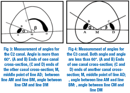
- Category II (C2): the canal shape resembled a semicolon resulting from a discontinuation of the “C” outline (Fig. 2b), but either angle or (Fig. 3) should be no less than 60°.
- Category III (C3): 2 or 3 separate canals (Fig. 2c and d) and both angles, and , were less than 60° (Fig. 4).
- Category IV (C4): only one round or oval canal in that cross section (Fig. 2e).
- Category V (C5): no canal lumen could be observed (which is usually seen near the apex only) (Fig. 2f ).
Fan’s Classification (Radiographic Classification)4,7
Fan et al. classified C-shaped roots according to their radiographic appearance into three types:
1. Type I: conical or square root with a vague, radiolucent longitudinal line separating the root into distal and mesial parts. There was a mesial and a distal canal that merged into one before exiting at the apical foramen (foramina) (Fig. 5a).
2. Type II: conical or square root with a vague, radiolucent longitudinal line separating the root into distal and mesial parts. There was a mesial and a distal canal, and the two canals appeared to continue on their own pathway to the apex (Fig. 5b).
3. Type III: conical or square root with a vague, radiolucent longitudinal line separating the root into distal and mesial parts. There was a mesial and a distal canal, one canal curved to and superimposed on this radiolucent line when running towards the apex, and the other canal appeared to continue on its own pathway to apex.

Figure 5.Radiographic types; a) type I, b) type II, c) type III
MANAGEMENT
After obtaining adequate local anaesthesia and isolation of the tooth to be treated, access cavity should be prepared.
Access cavity preparation1,3,8,9,10:
- After entering the pulp chamber with round diamond point and de-roofing the pulp chamber, walls of pulp chamber are flared with tapered diamond point to such an extent that all the canal orifices are clearly visible. This is known as straight line access. This eliminates the irregular walls in the pulp chamber allowing the instruments to negotiate the canals easily.
- The access cavity for c-shaped root canal system varies considerably and depends on the pulp morphology of the specific tooth (fig.6).

Figure 6. Straight line access
BIOMECHANICAL PREPARATION
After entire pulp extirpation and irrigating the canals with sodium hypochlorite, a No.8 or No.10 k-file should be used to go up to the working length.
This step will serve four purposes-
1) To check patency,
2) To determine the working length
3) To achieve the initial glide path
4) To make impression of the canal (fig.7).
Before removing file make a reference point to identify the direction of curvature. The impression of the canal on the file mirrors the degree, type, location and direction of curvature. Avoid using either a stainless steel file above No.10 in curved canals as they are not flexible. The entire procedure should be done under copious irrigation with warm 5% sodium hypochlorite and normal saline. EDTA should be used as lubricating medium.
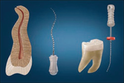
Figure 7.Making an impression
CLEANING AND SHAPING CANALS
- Cleaning is defined as removal of all the potentially pathogenic contents of the root canal system.
- Shaping is defined as the establishment of a specifically shaped cavity which performs the dual role of three dimensional progressive access into the canal and creating an apical preparation which will permit the final obturation instruments and materials to fit easily.
APICAL CURVES
If the impression shows that the curved canal is at the apical third, first do the coronal flaring using Gates Glidden drills and peizo in sequential manner, then measure the length with a K-file up to the curve. Use this straight-away length to instrument with 0.04% flare-files or 0.04% Ni-Ti rotary instruments in a crown-down fashion until the total straight-away length is negotiated (ie, up to the curve). Instrumentation beyond the curve with inflexible file or 0.04% rotary Ni-Ti instruments may perforate or ledge the canal. Making this “straight-away” will remove all of the restrictive dentin in the coronal and middle two thirds of the canal, which will facilitate subsequent files in reaching working length (fig.8).

Figure 8. Obtaining a straight-away length
After achieving patency, making an impression, creating an initial glide path, and crafting the straight-away, the next step is to create a well-defined glide path. This will make it easier to negotiate the canal and curve with subsequent instruments. To create a super glide path, instruments should be used in a step back technique; that is, first use a No.15 K-file (0.02% taper) or (0.02% No.15Ni-Ti) to working length; then use a No.20 K-file (0.02% taper) or (0.02% No.20Ni-Ti) to working length and, if possible finish with a NO.25 k-file(0.02% taper) or (0.02% be used in a crown-down fashion beyond the curve to working length; finishing with No.15K-file (0.04%) or 0.04% No.15 Ni-Ti. Recapitulate until

the master apical file reaches working length, which in a severely curved canal should be a No.20 or No.25. If the 0.04% tapers will not advance easily, use 0.02% tapers in a crown-down fashion and then return to the 0.04% tapers. Avoid using 0.06% rotary Ni-Ti tapers or protapers in a canal with a sharp curve as these wider tapers have less flexibility, increasing the chance of file separation
BANANA CURVES
If the impression shows a mid-root banana curve, obtain the straight-away length by measuring up to the apex. Because mid-root banana curves tend to be more gradual and less acute than apical curves, they allow for straight-away measurement all the way to the level of apex. This is unlike the straight-away in the acute apical curve, which stops at the very beginning of the curve. Then the mid-root banana curve can be negotiated with the 0.02% and then 0.04% k-files or Ni-Ti in sequential manner. Protaper can be used in such canals. Do not bend the instruments because this may create a ledge or perforation. Always direct the files away from the furcation so as not to strip or perforate the thin wall in that location.

S-SHAPED CURVES
S-shaped curve, usually found in upper premolars (Figure 11). Because S-shaped curves consist of two curves, they usually present a greater risk of file separation than the apical and mid-root banana curves, as the file must pass through both curves. Make a straight-away up to the beginning of the first curve. This length is usually short enough for the files alone to make the straight-away. Look at the impression to calculate the measurement, then create a super glide path to working length by using 0.02%K-files or 0.02% rotary Ni-Ti instruments in a step back technique

as described above ( No.15; No.20 and No.25). Then use these same in a crown-down fashion, from No.35 to No.15. Recapitulate until at least the master apical file reaches to working length, then start to crown-down with 0.04% K-files or 0.04% rotary Ni-Ti instruments. This technique, though requiring a greater number of files than the apical or mid-root banana curves, is safer because it helps prevent file separation.
C-SHAPED CANAL CONFIGURATION1,4,11,12
In all categories of c-shaped canal configuration, the mesiobuccal and distal canals can be prepared normally. However the isthmus should not be prepared with larger than no.25 files otherwise strip perforation can occur. Also Gates-Glidden burs should not be used to prepare isthmus areas. Extravagant use of small files and 5.25%NaOCl is a key to debride the narrow canal isthmuses. Avoid excessive use of chelating agents. Sonic and ultrasonic instruments can be used but their aggressive use may cause perforation. An anticurvature filing in coronal third of canal is strongly
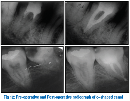
recommended to prevent perforation. If dentin filing is directed bucally, perforation can be avoided.
Obturation
Obturation can be done by lateral condensation technique using NiTi spreaders1,2,3,4,11,12.
REFERENCES
- Nisha Garg ;Textbook of Endodontics, Cleaning and shaping of root canal system,Pg.No.181.
- Ingle J I, Root canal preparation in ;PDQ Endodontics; B C Decker, Hamilton, Ontario 2005 pg. no.129.
- Nidhi Jain et al;Curved canals;ancestral files revisited,Dental research 2008,vol 19,issue 3,pg.no.267-271.
- Hamid Jafarzadeb et al, The c-shaped root canal configuration: a review; JOE, vol.33, no.5, May 2007, pg.no.517
- Melton D C et al; Anatomical and histological features of c-shaped canals in mandibular second molars J Endo 1991;17; pg.no.384-8.
- Fan B et al,C-shaped canal system in mandibular second molar;part-I anatomical features, JOE,2004;30; pg. no. 904-8.
- Fan B et al,C-shaped canal system in mandibular second molar;Part-II radiographic features, JOE,2004;30; pg. no. 904-8Vertucci F J, Root canal anatomy of the human permanent teeth.1984;58: pg.no.589-99.
- Melvyn Segal, Managing curved canals; the straight-away and super glide path technique; Inside dentistry, April 2008, vol 4, issue 4.
- Tzu-Yi Lu et al, Complicated root canal morphology of mandibular first premolar in chinese population using the cross section method, JOE-vol 32; no.10; oct 2006; pg.no.932.
- L.Stephan Buchanan; Managing sever canal curvatures and apical impediments: an endodontic case study,Dentistry today.com/.../1089.
- Vertucci F J,Root canal anatomy of the human permanent teeth,1984;58;Pg.No.589-599.
- Cohen S. et al; Pathways of pulp; 8th edition; st. Louis:Mosby2002;196-229.
Disclaimer from Guident
The views and opinions expressed in articles published in Guident are solely those of the authors and do not necessarily reflect the views of the editors, the editorial board or the publisher, Ivory India. Guident does not endorse any product, technique or treatment described. Clinical content is intended for qualified dental and medical professionals and is not a substitute for individual clinical judgement. Guident, its editors and the publisher accept no liability for any consequence arising from the use of information published in the journal.
How to cite this article
Dr. Abhijit B. Vajramushti. Management of Curved Canals and C Shaped Canal Morphology. Guident. 2014 Oct;7(11). Available from: https://ivoryindia.in/articles/endodontics/management-of-curved-canals-and-c-shaped-canal-morphology.html