Different Spacer Designs in Complete Denture Prosthodontics
Department of Prosthodontics And Crown & Bridge, Seema Dental College & Hospital, Rishikesh Uttarakhand, India
ABSTRACT
An Impression is the first step in the fabrication of a complete denture prosthesis. Many techniques are advocated for making impressions by various authors. Out of which the most acceptable is Boucher’s Selective Pressure Therory, Which may be achieved by scrapping the cast in selective areas or by the fabrication of a custom tray with proper spacer design with different materials & designs, adequate extensions, tissue stops, escape holes, tray handles, and polymerization time regarding custom impression trays in prosthodontics. This article will give a view to the dentists as per various clinical situations in their practice on tray handles, and polymerization time regarding custom impression trays in prosthodontics. This article will give a clear view to the dentists to the use of accurate spacer design, material and thickness, tissue stops, and escape holes, based on various clinical situations in their practice.
Keywords: Spacer Designs, Relief areas, Impression Techniques, Clinical situations.
INTRODUCTION
The need to make accurate impressions is the fundamental to practising prosthodontics, and thus it necessitates dentists to make careful assessment of the tissues to be recorded in the impression, the type of trays to be used, impression materials, and techniques to be used. There are four basic impression theories that have been proposed and accepted over the years being: Mucostatic, Mucocompressive, Minimal Pressure, Selective Pressure Techniques. Other being Muco-Seal Techniue, Impression by the use of sub-atmospheric pressure, Impression for compromised patients, Impression technique for patients with severely resorbed mandibular ridges.1-4
- Mucostatic/passive/non-pressure impresion technique
- Mucocompressive/pressure technique:
- Minimal compressed technique
- Selective pressure technique
1938/1946 Proposed by Henry Page on Pascals Law. According to which the oral mucosa is recorded in resting/static state. Using oversized impression trays with spacer. Border moulding is not performed and so flanges are shorter than other techniques. The material of choice is Impression Plaster. Disadvantages being: Deprivation of maximum coverage of denture bearing areas within physiologic limits, Resulting in closely adapting dentures causing lack of retention, unasthetic dentures, but due to close peripheral seal they are stable.
1896. Proposed by Greene Brothers. In which the tissues are recorded in functional state by compressing the denture bearing areas. Use of high viscosity impression materials, impression compounds,irreversible hydrocolloids, putty & heavy body elastomeric impression materials, Closed mouth technique also provides mucocompressed impressions. This technique was not promoted much as it will lead to continuous pressure which will lead to residual ridge resorption. It will also compromise denture retention, as the displaced tissue rebounds when in rest. So the denture will dislodge at rest or while speaking. The tissues are uniformly compressed so even the areas which are supposed to be relieved are under pressure, leading to good initial retention but eventual resorption and loose dentures.
It is a commprehension between Mucocompressed and Mucostatic Impression Technique. In it a minimal pressure is applied, which is a little more than that of a free flowing material. The disadvantage is that there is a lack of standardized protocol regarding the pressure to be applied during the impression.
It was Proposed by Carel O Boucherr in 1950. It combines the principles of both Pressure and minimal pressure techniques. The pressure is applied minimally on the areas which are capa; ble of resisting stress, i.e. the stress bearing areas. And reduced from the areas which are incapable of bearing stress i.e. the Relief areas. The spacer design for the selective pressure technique is thus directly governed by the knowledge of the stress-bearing and relief areas.
For the maxilla the Primary Stress bearing area is the horizontal slopes of the hard palate lateral to the median suture and the Secondary Stress Bearing areas are the Crest Of the Residual Alveolar Ridge, Rugae, Maxillary Tuberosity. While the Relief Arreas are: Midpalatine Suture, Incisive Paoilla and the Torus Palatinus.
While for the Mandible The Primary Stress Bearing Area is the Buccal Shelf area and the Secondary stress bearing area is the labial and lingual slopes of the residual ridge. The Relief areas are; Crest of the Residual alveolar ridge, Mylohyoid Ridge, Mental Foramen, Genial Tubercles, Torus Mandibularis.
Selective Presuure may be achieved by scrapping the primary cast/impression in the selective areas or by the fabrication of a custom/special tray with proper spacer design with different materials & designs, adequate extensions, tissue stops, escape holes for relief. The latter is a better method as it is more accurate with the thickness of the spacer material(wax spacer) we can achieve compression on tissues in different areas(Stress Bearing Areas)
However views of different authors on how to achieve selective-pressure impression are different. Though custom impression trays are used for making final impression in complete denture, there is improper knowledge of custom-impression tray designs among dentists and thus making them dependent on their technicians to do so.2
THE CLASSIFICATION OF SPACER DESIGNS
- FULL SPACERS: It is made to cover the whole residual ridge except PPS area in maxilla and buccal shelf and retromylohyoid area in the mandible. Thus providing space for impression material.
- PARTIAL SPACERS: Based on clinical needs. It is made to cover specific areas only. Like the T shape and I Shaped Spacer.
- SPACERS WITH TISSUE STOPPERS: Tissue stoppers/ windows are made bilaterally at the canine and the molar region mostly 2mm in width. They help in proper vertical seating of the impression tray, they and control the thickness of the impression material.5
MATERIALS USED FOR MAKING SPACERS:
- Tin foil: As recommended by Roy Mac Gregory in the region of incisive papilla and midpalatine raphe
- Casting wax: As recommended by Neil. In thickness of 0.9 mm to be adapted all over except PPS area.
- Nonasbestos ring liner (wet): Used shellac is used for custom tray fabrication
- Base-plate wax: Used as a spacer mostly when acrylic resin is used for custom tray fabrication.6
Thickness of the wax spacer
A Spacer for completely or partially edentulous cases are generally 1-3mm thick. But the thickness depends on the type of impression material used for making secondary impressions and the demand of the clinical situation. Like:
- 2 mm spacer with tissue stops 0.5 mm spacer: Used when Impression Plaster or Zinc Oxide Eugenol is being used for making impression in cases of non undercut ridges.
- 3 mm spacer with tissue stops: Used with Alginate for Non undercut and undercut ridges.
- 1.5 mm spacer with tissue stops: Used with Polysulphide elastomeric impression material for undercut or non undercut ridges.
- 3mm spacer: Used with Silicones for Undercut and non undercut ridges.
- Nonspecified: In cases of Different Clinical situations and demands the spacer thickness and design varies. Like for displacable tissues.
TISSUE STOPS: Are to be placed strategically. They provide even thickness of the impression materials in the custom tray. Tissue stops are made by removing wax at a 45 dergree angle to the occlusal surface which will have a tripod or quadangular arrangement on the arch. This provides stability to the tray and will help centre the tray during insertion.
DIFFERENT SPACER DESIGNS WITH VARIOUS CONCEPTS
1. BOUCHERs: He advocates the placement of a 1mm thick baseplate wax within the outlined border on the cast to provide space for the final impression. He suggests not to cover the posterior palatal Seal Area with the wax spacer so that the custom tray touches the mucosa directly and the additional stress placed here during impression making would create a posterior palatal seal. Also this part of the tray will act as a guiding stop to help position the tray properly during impression procedures. In the mandible 1 mm thick base-plate wax covers the mandibular ridge except buccal shelf area and retromolar pad area.1 He has also advocated the placement of Escape holes in the palatal area using 6mm round burs.
He says a wax spacer must not be used in cases when metallic oxide impression paste has been selected for making final impressions.1 Fig.1.

Fig. 1
2. MUROW, RUDD and RHOADS: It is based on the Minimal Pressure Technique. Firstly beginning with marking an outline on the cast where the borders are usually shorter than the vestibular depth, and the posterior border is marked as a line extending between the two hamular notches with a midpoint 2mm distal to the fovea palatina, The undercuts are then blocked with wax and a layer of baseplate wax is adapted to the cast for relief (2mm short of the resin custom tray borders) With the placement of 3 tissue stops, 4mm equidistant from each other.4 Fig. 2.

Fig. 2
3. SHARRY: It is also based on the Minimal Pressure Technique and advocates the adaptation of a layer of baseplate wax even on the PPS area and giving 4 tissue stops in the molar and cuspid regions 2mm in width running from the buccal to the palatal aspect of the ridge to the muccobuccal fold. Also placing a vent hole in the incisive papilla region. To be used while taking Final impressions from metallic oxide impression materials.7 Fig. 3.


Fig. 3
4. BERNARD: On the Selective Pressure Technique, he recommends placing a layer of pink baseplate wax on the areas of soft tissue. And making the spacer all around except on the posterior part of the palate which are at high angles to the occlusal forces and also not on the midpalatine raphe which is usually relieved in other designs but he says it acts as a stopper.8 Fig. 4.
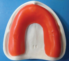
Fig. 4
5. HALPERIN: He recommends making a custom tray by giving Peripheral relief by providing 1 mm thick wax relief over the peripheral extensions and buccal slope region of tray including PPS and that the custom tray be in intimate contact with basal seat areas. Which makes the internal finish lines to form a butt joint of the compound to the tray after border molding is completed. No secondary wash impression is needed. As the tray surface and border-molded areas acts as final impression surface itself. Thus a master cast is directly poured into bordermolded trays.9 Fig 5.


Fig. 5
6. ROY MAC GREGOR: Rcommends placement of a sheet of metal foil in the region of incisive papilla and midpalatine raphe. It is based on the selective pressure technique. He says that the other areas which must be relieved are the maxillary rugae, other areas which are subject to mucosal damage, buccal surface and the prominent tuberosities. But he says that relief need not be given routinely in the dentures.10 Fig 6.

Fig. 6
9. NEIL: He recommends adapting 0.9mm of casting wax all over except on the PPS area.11 Fig. 7.

Fig. 7
10. HEARTWELL: Has recommended the use of two techniques to achieve selective pressure for the maxilla. In the first he says to make a primary impression with impression compound in a nonperforated stock tray; the borders are refined. Then, space is provided in selected areas by scraping of the impression compound. In the second technique, he recommends the fabrication of a custom tray (but did not mention about the wax spacer). Border molding is done with low fusing compound. He recommends the placement of five relief holes on the palatal region,three in the rugae area and two in the glandular region, before making the secondary impression with zinc oxide eugenol paste.12
11. SHELDON: Also describes two techniques. First involving the use of low-fusing modelling compound (Kerr white cake compound) to make the primary impression and borders are refined with Kerr green stick compound. Once the operator is satisfied with the retention, selective relief is accomplished by scraping in the region of incisive papilla, rugae, and mid palatine area. While in the second technique, he describes of making a primary impression with alginate. Undercuts are blocked out. Then, he recommends the placement of spacer or pressure control but he did not mention clearly about the wax spacer design. Border molding is done with green stick compound before making the secondary impression with ZOE paste13, based on selective-pressure technique used on high arched palate.
12. SHETTY: Described a technique in which a thin wax of 0.4mm major connector wax (Germany) is to be placed in all areas except the PPS as this area needs to be compressed during the border-molding procedures. Then a 1.5 mm thick layer of modelling wax is applied on top of the already adapted wax sheet. The modelling wax is removed in the region of the crest of the alveolar ridge and the horizontal palates as these are the stress-bearing areas.14
13. SMITH: According to his design a 1 mm thick base-plate wax covers the ridge and midpalatine raphe then two tissue stops are placed at the canine region and exposed hard palate, which will help in the vertical seating of the tray and will also control the thickness of impression material.15 Fig 8

Fig. 8
OTHER DESIGNS 5
- Minimal-pressure technique for the maxillary arch
- Selective-pressure technique for the mandibular arch:
Based on the minimal-pressure technique, a 1 mm base-plate wax is placed over the basal area except on the right and left posterior hard palate. Then four tissue stops, are made at the canine and molar region. The material of choice is rubber generally.16-20
Based on the selective-pressure technique, a 1 mm thick base-plate wax is placed over the entire alveolar ridge except at the retromolar pad area. Tissue stops are placed, each at canine region, bilaterally. Which will provide uniform thickness of the impression material. The exposed retromolar pad acts as the stress-bearing area.21-25
Partial spacers are given as they cover specific areas:
a. T Shape Spacer: It is based on the Selective Pressure Technique. It covers the anterior residual alveolar ridge in the maxilla when it is flabby and resorbed. It also covers the prominent incisive papilla, rugae and midpalatine raphe, and the exposed areas act as stoppers. Partial spacer designs in the mandible cover only the anterior residual alveolar ridge when it is resorbed, flabby or atrophied.26-29 Fig 9


a. Fig 9
b. I Shape Spacer: it is based on the Selective Pressure Technique. In the Maxillary Arch it covers the Midpalatine Raphe, Incisive Papilla.30 Fig 10

Fig 10
CONTRAINDICATIONS FOR USING SPACER
In cases of highly resorbed ridges, spacer is not used as a solid tray is easier to manage. In such cases, carbide bur can be used to remove about 1 mm of the custom tray material from the crest of ridge area.
CONCLUSION
While making impression, one should apply pressure selectively only in certain areas, which can withstand the forces of mastication. The use of Custom Trays with Relief and escape holes for selective pressure of the edentulous ridges, regardless of the type of impression material used results in the distribution of pressure so that the impression force is decreased and the bite pressure is transferred to the stress bearing areas which inhibits soft tissue abuse and bone resorbtion.
This article shows that a varied range of spacer designs are available for different clinical situations. And based on the particular demand, the dentist needs to select the spacer design for the success of of the prosthesis to be made.
REFERENCES
- Boucher CO (1951) A critical analysis of mid-century impression techniques for full dentures. J Prosthet Dent 1: 472-490.
- Zinner ID, Sherman H (1981) An analysis of the development of complete denture impression techniques. J Prosthet Dent 46: 242-249.
- Zarb GA, Bolender CL, Carlsson GE (1999) Boucher’s Prosthodontic Treatment for Edentulous Patients. 11th ed. St. Louis, MO: Mosby, pp. 3123-3123.
- Morrow RM, Rudd KD, Rhoads JE (1986) Dental Laboratory Procedures, Complete Dentures, Vol. 1, 2nd ed. Toronto: CV Mosby, pp. 26-56.
- Winstanley RB, Carrote PV, Johnston A (1997) The quality of impressions for crowns and bridges received at commercial dental laboratories. Br Dent J 183: 209-213
- Devlin H, Cash AJ, Watts DC (1995) Mechanical behaviour and structure of light-cured special tray materials. J Dent 23: 255-259.
- Sharry JJ (1974) Complete Denture Prosthodontics, 3rd ed. New York: Blakiston, pp. 191-210.
- Bernard L (1984) Impressions for Complete Dentures. Chicago, IL: Quintessence, pp. 71-90.
- Halperin G, Rogoff P (1988) Mastering the Art of Complete Dentures. Chicago, IL: Quintessence, pp. 43-51.
- Mac Gregor Roy A (1994) Fenn, Liddelow and GImson’s Clinical Dental Prosthetics, 3rd ed. Oxford: Wright, Butterworth, pp. 43-77.
- Neill DJ, Nairn RI (1990) Complete Denture Prosthetics, 3rd ed. London: Wright, pp. 22-26.
- Rahn AO, Heartwell CM (2002) Text Book of Complete Dentures, 5th ed. India: Elsevier Science, pp. 221-247
- Sheldon W (1996) Essentials of Complete Denture Prothodontics, 2nd ed. Philadelphia, PA: Ishiyaku Euro America, pp. 88-106
- Shetty S, Nag PVR, Shenoy KK (2007) A review of the techniques and presentation of an alternate custom tray design. JIPS 7: 8-11
- Smith PW, Richmond R, McCord JF (1999) The design and use of special trays in prosthodontics: guidelines to improve clinical effectiveness. Br Dent J 187: 423-426.
- Herekar M, Sethi M, Fernandes A, Kulkarni H (2013) A physiologic impression technique for resorbed mandibular ridges. J Dent Allied Sci 2: 80-82.
- Frank RP (1969) Analysis of pressures produced during maxillary edentulous impression procedures. J Prosthet Dent 22: 400-413.
- Ohkubo C, Watanabe I, Tanaka Y, Hosoi T (2003) Application of cast iron— platinum keeper to a collapsible denture for a patient with constricted oral opening- a clinical report. J Prosthet Dent 90: 6-9.
- Baker PS, Brandt RL, Boyajian G (2000) Impression procedure for patients with severely limited mouth opening. J Prosthet Dent 84: 241-244.
- Geckili O, Cilingir A, Bilgin T (1982) Impression procedures and construction of a sectional denture for a patient with microstomia: a clinical report. J Prosthet Dent 96: 387-390.
- Manish KS, Vijay K (2010) Comparative evaluation of the accuracy of different materials used for fabrication of custom impression trays to make impression in partially edentulous situations. B F U Dent J 2: 9-11.
- Goldfogel M, Harvey WL, Winter D (1985) Dimensional change of acrylic resin tray materials. J Prosthet Dent 54: 284-286.
- Pagniano RP, Schied RC, Clowson RL, et al. (1982) Linear dimensional change of acrylic resins used in the fabrication of custom impression trays. J Prosthet Dent 47: 79-283.
- Cura C, Cotert HS, User A (2003) Fabrication of a sectional impression tray and sectional complete dentures for a patient with microstomia and trismus: a clinical report. J Prosthet Dent 89: 540-543.
- Luebke RJ (1984) Sectional impression tray for patient with constricted oral opening. J Prosthet Dent 52: 135-137.
- Giordano R (2006) Materials for chair side CAD/CAM—produced restorations. J Am Dent Assoc 137: 14-21.
- Giordano R (2006) Materials for chair side CAD/CAM—produced restorations. J Am Dent Assoc 137: 14-21.
- Christensen GJ (2008) Will digital impressions eliminate the current problems with conventional impressions? J Am Dent Assoc 139: 761-763.
- Basker RM, Ogden AR, Ralph JP (1993) Complete denture prescription—an audit of performance. Br Dent J 174: 278-284
- Sheldon W (1996) Essentials of Complete Denture Prothodontics, 2nd ed. Philadelphia, PA: Ishiyaku Euro America, pp. 88-106.
Disclaimer from Guident
The views and opinions expressed in articles published in Guident are solely those of the authors and do not necessarily reflect the views of the editors, the editorial board or the publisher, Ivory India. Guident does not endorse any product, technique or treatment described. Clinical content is intended for qualified dental and medical professionals and is not a substitute for individual clinical judgement. Guident, its editors and the publisher accept no liability for any consequence arising from the use of information published in the journal.
How to cite this article
Dr. Yogeshwari, Dr. Himanshu Aeran. Different Spacer Designs in Complete Denture Prosthodontics. Guident. 2019 Nov;12(12). Available from: https://ivoryindia.in/articles/prosthodontics/different-spacer-designs-in-complete-denture-prosthodontics.html