CAD-CAM Fabrica Ted Complete Denture- a PEEK into the Future...
Department of Prosthodontics, Srinivas Institue of Dental Sciences Surathkal, Mangalore, India, Department of Conservative & Endodontics, Srinivas Institue of Dental Sciences Surathkal, Mangalore, India, Department of Prosthodontics, K.D Dental College & Hospital, Mathura, (U.P), India
INTRODUCTION
The acronym CAD/CAM represents Computer-Aided Design (CAD) and Computer-Aided Manufacturing (CAM). With this design and manufacturing technology, CAD software defines the geometry of an object while CAM programming directs the fabrication process.
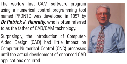
The CAM manufacturing component was actually developed in advance of the CAD technology. In the 1950’s, manufacturers first adopted tools controlled by a system of numbers and letters to produce objects with complex shapes in both an accurate and repeatable manner (Numerically Controlled or NC).
This resulted in a lasting linkage between CAD and CAM software and machinery, and the technology expanded from that point forward.
Initial dental applications
In the early 1980s, CAD/CAM technology was used to produce clinical dental restorations when Andersson envisioned the use of titanium for the fabrication of crowns. In 1982, Andersson developed the CAM portion of the fabrication process by using a combination of spark erosion and copy milling. In that same year, he cemented the first CAM fabricated titanium complete crown.
Andersson quickly recognized that the potential commercialization of the process would be costly and the resulting fabrication processes would involve digitization, a realization which then led to the development of the CAD fabrication process. His pioneering activities became commercially available as the Procera method of fabricating crowns in 1983. The Procera system was subsequently acquired by Nobelpharma (now Nobel Biocare) in 1988.
Another important dental application of CAD/CAM technology also occurred in the 1980s. Mörmann developed an interest in tooth-colored restorations. He wanted dentists to be able to produce durable inlay restorations chairside by scanning cavity preparations intraorally and using the resulting CAD data to form a ceramic restoration that would fit the prepared tooth by using CAMtechnology. Mörmann developed a prototype CAD/CAM device in 1983, and a system became fully functional in 1985. In September of that same year, Mörmann placed the first chairside fabricated ceramic restoration with equipment introduced and marketed as the CEREC 1 system.
The design and milling of single crowns, partial fixed dental prostheses, and a variety of implant components and prostheses have since become relatively common clinical and laboratory procedures. Despite these many advances, CAD/CAM technology has yet to be used for the fabrication of conventional complete dentures.

In the future, it will be possible to scan the morphology recorded by using this technique and to transfer that digital data to a CAD software program where denture teeth can be virtually placed intoappropriate positions.
Then a dental laboratory technician can export the denture base form and tooth arrangement morphology to a milling machine for the fabrication of the maxillary and mandibular complete dentures. As an additional step beyond this clinical technique, a prototype CAD program, known as the 3D Tooth Arrangement Program, was developed by the Charles J. Goodacre aided by computer programmers in 2009.
The purpose of this article is to review the clinical procedures required to record the morphology of the intaglio and cameo surfaces of complete denture bases as well as the locations suitable for the placement of prosthetic denture teeth, for fabrication of the denture through CAD-CAM.
ADVANTAGES OF CAD-CAM DENTURES
- It is possible to record all the clinical data for complete dentures in one appointment (one to two hours).
- Clinical chair time is reduced considerably, thereby providing the opportunity for a more cost-effective set of appropriately accurate complete dentures.
- A repository of digital data remains available that allows for more rapid fabrication of a spare denture, a replacement denture, or even a radiographic or surgical template that aids in the planning and placement of dental implants in the future.
- Additionally, because the digital data are associated with a specific practitioner, it is more likely that patients will return to the dentist who fabricated their first digital denture when future treatment is needed.
- Because the denture base is fabricated by machining, polymerization shrinkage of the resin is eliminated, and the fit of the denture base is superior to that of conventionally fabricated denture bases.
- Due to the method of processing the acrylic resin for denture bases at fifty times the conventional processing pressure, there is less porosity.
- Initial research reveals that the AvaDent™ denture base material may have less C. Albicans adherence.
CLINICAL TECHNIQUE
The following technique includes all the requisite steps required to produce maxillary and mandibular definitive impressions of the edentulous arches in a manner that will permit the application of CAD/CAM technology.
The overall goal is to make definitive edentulous impressions that capture the edentulous ridges and borders (vestibules) while recording as much as possible of the functional soft tissue that will be in contact with the facial surfaces of the denture bases located occlusal to the denture borders.
Additionally, the impressions should record muscular and phonetic positions suitable for placing prosthetic denture teeth.
Impression trays

The edentulous impressions can be made by using either a custom tray or a stock tray that can be molded to conform to the shape of each patient’s arch and provide the required border extensions.
Mandibular impression making
After the impression tray has been selected (custom or stock tray), and conformed to the patient’s mouth, border molding is then performed using a medium-body vinyl polysiloxane impression material. A light-body impression material is then used to complete the mandibular impression.
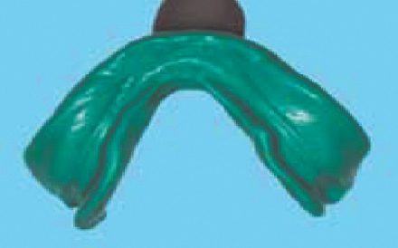
The mandibular posterior neutral zone impression technique
Once the border molding and definitive impression is completed, an accompanying neutral zone impression is made on the occlusal surface of the tray.
Medium-body vinyl polysiloxane impression material is dispensed along the entire occlusal surface of the tray, from each retromolar pad area of the tray to the handle, at a vertical height sufficient to reach the level of the center of the retromolar pads bilaterally. The impression is then promptly placed intraorally, and the patient asked to swallow 3 times in succession while pressing their lips together and pressing their tongue laterally against their lips and cheeks.
After completing these movements, the patient is instructed to relax the mandible and tongue and the impression can be removed.

The repeated swallowing results in compression of the impression material between the lower lip, cheeks, and tongue muscles, thereby recording the location of the posterior neutral zone.

Mandibular anterior tooth positioning impressions
Sometimes the mandibular tray handle interferes with the lingual morphology of the anterior aspect of the neutral zone impression. When this occurs, the tray handle should be removed along with any impression material that may be covering the occlusal aspect of the tray in the area where the mandibular anterior teeth will be located.

Impression material adhesive is applied and medium-body impression material is dispensed over this exposed anterior region, the tray is placed intraorally, and the patient is instructed to swallow once and then pronounce the letters “Q” and “U” 3 times consecutively to mold the lingual area. After the patient completes these sounds, the material is trimmed so that it is level with the posterior neutral zone areas.

Production of the sounds required to form the letters, “Q” and “U”, activates the muscles of the chin as well as those muscles associated with the mentolabial angle and in turn, create the form of the mandibular anterior denture base.

Maxillary impression making
As with the mandible, maxillary edentulous impressions can be made with either a custom or stock impression tray. The posterior extension of the tray is determined by the location of the vibrating line that delineates the transition between the immovable hard palate tissue and the movable tissue of the soft palate. Next, the maxillary impression is made so as to accurately record the edentulous ridge morphology and the border extensions. On the facial surface of the tray, the light-body impression materialshould be extended as far aspossible occlusally beyond the borders (flanges) by muscular and manipulative movements made during the border molding. It is through this process that the tissue contacting facial surfaces of thedenture are formed.

Clinical technique for establishing palatal morphology
The morphology of the palate is recorded by placing medium-body vinyl polysiloxane impression material onto the cameo surface of the palate, replacing the impression intraorally, and instructing the patient to read the 13 stimulus sentences aloud.

Rather than attempt to capture the entire palate in 1 seating, a 2-step process is recommended. First, the posterior aspect of the tray is thinned, and then a 3 mm thickness of medium-body vinyl polysiloxane impression material is placed in the area of the second molars bilaterally and across the posterior border of the tray. Secondly, to capture the remaining form of the palatal slope, a3-mm thick layer of medium-body impression material is dispensed onto the remainder of the palate and the patient is immediately instructed to read the first 12 stimulus sentences in order.

There are no speech sounds that establish the contours of the central portion of the palate. This portion of the denture base is formed by producing a smooth transition between the previously developed palatal morphology on 1 side of the arch with the corresponding palatal contour on the opposite side of the arch and developing the appropriate thickness in the central area of the palate on the digitized impressions.
Clinical technique for determining maxillary anterior tooth positions
The faciolingual and incisocervical locations of the maxillary anterior prosthetic teeth have traditionally been determined by using tooth visibility and lip support. Phonetics and the lip position at rest also can be used to help identify the area where denture teeth can be appropriately located.
To determine anterior tooth positions with these guides, the tray handle is removed along with the impression material located over the occlusal aspect of the tray and medium body vinyl polysiloxane impression material is placed over the anterior ridge crest area. The patient is instructed to pronounce the word “thank” followed by pronunciation of the letter “V”. This combination is pronounced 3 times and then the word “thank” is repeated an additional 3 times.

When pronouncing the word “thank”, the tongue molds the lingual aspect of the impression material and helps to locate the approximate faciolingual position of the lingual surfaces of the anterior teeth. Pronouncing the letter, “V”, helps to identify the incisal length of the impression material and thereby establishes the approximate location of the incisal edge of the maxillary central incisors.
Following polymerization of the impression material, the facial half of the anterior impression material is removed to expose the tray, the area coated with adhesive, and the impression material deposited into the recess. The patient is instructed to pronounce the letters “Q” and “U” 3 times and then relax their tongue and lipsfor several seconds so the upper lip can rest against the impression material and establish an approximate anteroposterior position for the maxillary anterior teeth.

The upper lip is then grasped and pulled facially so the impression can be removed without disturbing the incompletely polymerized impression material.
Occlusal vertical dimension, tooth positioning, and interocclusal records
The occlusal vertical dimension is established by using any one of several appropriate methods and marks placed on the skin for future reference. The maxillary and mandibular impressions are used as record bases to establish the occlusal vertical dimension and make interocclusal records.
The impressions are both seated simultaneously to evaluate the amount of impression material and tray material that typically has to be removed posteriorly because it interferes with proper mandibular closure at the established occlusal vertical dimension. Following complete closure without interference between the 2 impressions, a scalpel is used to create notches in the impression material and exposed tray material if present.
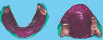
The maxillary impression is placed intraorally so the midline can be marked on the impression with a permanent marker and the buccal corridor space can be assessed.
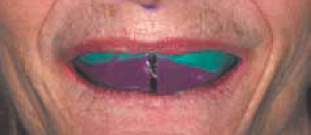
Then the maxillary anterior prosthetic teeth selected at the initial diagnostic appointment are arranged into the area now occupied by impression material. Facial and lingual putty indices of the form of the maxillary anterior phonetic impression can be made for use as guides in arranging the anterior teeth.

To arrange the maxillary anterior teeth, impression material is removed along with the required amount of tray material to create space for the addition of wax where the prostheticanterior teeth are located. Once arranged, the positions of the anterior teeth are verified intraorally for proper phonetics and modified as necessary to meet the patient’s esthetic requirements.

The occluding surfaces of the notched impressions are coated with a thin layer of petroleum jelly. Then the 2 impressions are reseated clinically and a small amount of soft wax is placed onto selected areas of the notched impression material as needed so that mandibular closure at the established occlusal vertical dimensionwill result in stabilized positioning of the impressions against the edentulous arches.
A vinyl polysiloxane interocclusal record material is injected intraorally so it can flow into the notched occlusal surfaces and around the teeth. The patient’s mandible is then immediately guided to its retruded contact position, and the mandible is closed to the appropriate occlusal vertical dimension where it is maintained motionless until the interocclusal record material is completely polymerized. A protrusive interocclusal record can also be made by using the notched impressions.

At this stage, the impressions and interocclusal record are scanned, the teeth arranged virtually in the scanned impressions, and the surfaces of the bases refined in the computer. The resulting data is then exported to a milling machine for fabrication of the dentures.

The 3-axis milling machine and large milling tool used in this first proof-of-concept denture resulted in a denture base with substantial milling lines, but the clinical procedures were validated.

Subsequently, the process focused on the refinement of the base milling by using a 5-axis milling machine and fine milling tools. Additionally, a posterior palatal seal technique was developed whereby a seal was created by “carving” it into the virtual cast based on clinical measurements that identified the appropriate location, form, and depth of the seal. The form created in the virtual cast was then applied to the scanned image of the impression so a seal would be present in the milled denture.
Recently, the previously described procedures have been used to scan clinical records, create and articulate virtual casts, arrange the teeth, and virtually form the bases.

The resulting data were used to mill a denture base from a block of pink denture base resin with recesses into which conventional denture teeth were bonded.

AVADENT ™ DIGITAL DENTURES
Recently, CAD/CAM technology has become commercially available for fabrication of complete dentures through the introduction of AvaDent™ digital dentures by Global Dental Science, LLC.
It is a system by which impressions, interocclusal records, and tooth selection can be completed in one appointment. The dentures are then fabricated using CAD/ CAM technology and placed in the second appointment.
The AvaDent™ digital denture process is designed to capture the necessary information for the fabrication of complete dentures in one appointment without compromising prosthesis quality.
The entire digital CAD/CAM process consists of the following appointments:
1. Impressions, jaw relation records, occlusal plane orientation, tooth mold and shade selection, and maxillary anterior tooth positioning record
2. Placement of dentures
APPOINTMENT 1
Making maxillary and mandibular final impressions:
Impression is made either in a custom tray or in a customized stock tray using medium body poly (vinyl siloxane) impression material is used to border mold the maxillary and mandibular trays and final impression is made by light-body poly (vinyl siloxane) impression material.
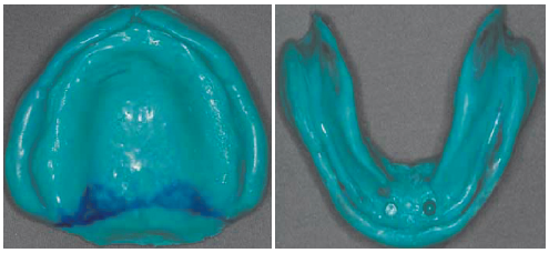
Jaw relation records
The AvaDent™ denture technique uses an Anatomical Measuring Device (AMD) that can be adjusted to the desired occlusal vertical dimension and then used to maintain that dimension while centric relation is recorded using the incorporated gothic arch tracing plate and stylus. The AMD is also used to determine the correct amount of upper lip support, the position of the maxillary six anterior teeth, and the desired mediolateral orientation of the occlusal plane.

The maxillary AMD is filled with AvaDent™ registration material and seated to record the ridge morphology of the maxillary arch as well as the portion of the palate covered by the AMD.

The mandibular tray with the recording plate is then filled with the recording material and used to stabilize the tray in the patient’s mouth. The occlusal vertical dimension is determined using the conventional methods. The adjustable screw in the maxillary tray is turned clockwise to extend the stylus, or counterclockwise to retract the stylus so that it contacts the mandibular tracing plate at the appropriate vertical dimension.

Once the vertical dimension has been established, the adjustable screw in the maxillary AMD is used to extend or retract the upper lip support flange so that it provides adequate
lip support. The patient is given an opportunity to assess the adjustments by viewing his/ her lips in a mirror.

Recording centric relation is accomplished by making an intraoral gothic arch recording.

A recess is then made in the tracing plate that approximates the tip diameter of the stylus at the apex of the gothic arch arrow point and the patient is guided to the position where the maxillary stylus engages the recess and maintain the centric relation position.

Occlusal Plane Orientation, Maxillary Anterior Mold and Shade Selection, and Maxillary Anterior Tooth Positioning
To record the occlusal plane orientation, the AvaDent™ ruler is inserted in the maxillary AMD and the anterior adjustable portion moved until it is aligned parallel to the imaginary interpupillary line connecting the centers of the pupils of the eyes.

The next procedure in this first appointment is to mark the midline on the lip support flange as well as the smile line for the maxillary anterior teeth based on the curvature of the lower lip during smiling.

The size of the maxillary anterior teeth is then determined by using the three available tooth size templates. It can be used on the teeth in the existing denture, assuming the existing denture tooth size is desirable to the patient. Or, to serve as a guide during denture fabrication, flowable composite resin is applied to the inside of the selected tooth mold template which is then positioned carefully over the midline and smile line markings and placed in the exact location where the denture teeth should be arranged.

AvaDent™ registration material (or another interocclusal record material) is injected into the space between the maxillary and mandibular arches, with the jaw stabilized in centric relation. The interocclusal record assembly is then removed and inspected to confirm that the stylus is in the centric relation recess and that the AMDs are firmly interlocked.

After following normal disinfection protocol, the final impressions and connected AMDs (along with the completed laboratory authorization form) are mailed to the Global Dental Science, LLC, producer of AvaDent™ digital dentures, along with any special instructions.
The company processes the impression and the AMD so that they can be more easily recorded during the laser scanning process.
The laser scans of the impressions and connected AMDs are made and the morphologic data merged so as to establish the occlusal relationship of the complete arch data obtained from the complete arch impressions.
The denture borders are identified and marked using the computer software, teeth are set virtually so that they occlude properly and have the desired occlusal plane orientation, and the morphology of the denture base is established.

Once the denture has been designed virtually, the denture base is milled with recesses that accurately fit each denture tooth and the teeth are bonded with a proprietary bonding mechanism.

APPOINTMENT 2

SUMMARY
The use of CAD/CAM technology to fabricate complete dentures has positive benefits for both the patient and practitioner. Theability to reduce the time required to provide patients with dentures and the potential to reduce the cost of care for patients while still providing quality dentures using state of the art dental materials is promising.It is anticipated that the fabrication of complete dentures will be commercially available with CAD/ CAM technology.
BIBLIOGRAPHY
- Cad/Cam Fabricated Complete Dentures: Concepts And Clinical Methods Of Obtaining Required Morphological Data. (J Prosthet Dent 2012;107:34-46).
- Cad/Cam Technology: Application To Complete Dentures (Loma Linda University Dentistry Summer / Autumn 2012, Vol 23, No. 2:16-23)
- Trial Of A Cad/Cam System For Fabricating Complete Dentures. (Dental Materials Journal 2011; 30(1): 93–96).
Disclaimer from Guident
The views and opinions expressed in articles published in Guident are solely those of the authors and do not necessarily reflect the views of the editors, the editorial board or the publisher, Ivory India. Guident does not endorse any product, technique or treatment described. Clinical content is intended for qualified dental and medical professionals and is not a substitute for individual clinical judgement. Guident, its editors and the publisher accept no liability for any consequence arising from the use of information published in the journal.
How to cite this article
Dr. Manoj Varma, Dr. Lavanya Varma, Dr. Prateek Agrawal. CAD-CAM Fabrica Ted Complete Denture- a PEEK into the Future. Guident. 2013 Apr;6(6). Available from: https://ivoryindia.in/articles/prosthodontics/cad-cam-fabrica-ted-complete-denture-a-peek-into-the-future.html